

In this article, we will see how to take your first steps with the Arduino UNO development board building a simple project from scratch.
What is Arduino?
Arduino designs, creates and supports electronics devices and software that make it easy for people to create their own projects.
Arduino offers various development boards that allow you to build a low-cost prototype.
Many people find it hard to believe, but Arduino was born in Italy (more precisely in Ivrea). If you want to learn more about how the project was born, I recommend watching this video, and to discover all the products offered by Arduino, visit their official website https://www.arduino.cc/.
The Arduino UNO board
The most well-known board is the Arduino UNO:
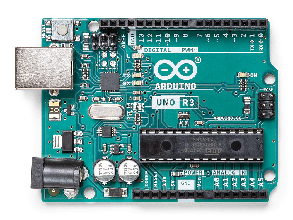
The Arduino UNO board is based on the ATmega328P microcontroller. It has 14 digital pins (6 of which can be used as PWM outputs) that can be used as inputs and outputs, and another 6 analog pins that can also be used as inputs and outputs.
Shopping bag
To start with Arduino, you have two options:
- Use the free online simulator Tinkercad by Autodesk, accessible at this link https://www.tinkercad.com/
- Buy an Arduino kit from the official website (https://www.arduino.cc/en/hardware#kits) and experiment with projects by hand.
How to create a project with an Arduino board?
Creating a project using an Arduino board always consists of two steps:
- Building the electronic circuit
- Writing a program to upload to the Arduino board
When you build the circuit, you use a breadboard, the Arduino board, electronic devices, and jumper wires to connect everything together (if you are using Tinkercad, you’ll simulate the same process).

In the second step, you write a program in Wiring language (don’t be intimidated, it’s very similar to C) and upload it to the Arduino board using the free Arduino IDE software (https://www.arduino.cc/en/software) by connecting the development board to your computer via USB (with Tinkercad, you write the program directly and start the simulation).
Basic Use of the Tinkercad Interface
Before we proceed with our first project, let’s briefly see how the Tinkercad interface works.
Tip: Even if you have an Arduino kit, it’s always convenient to create your projects on Tinkercad and have them easily accessible.
After registering or logging in (register as a student or personal account) at https://www.tinkercad.com/, the home page of your profile will open:
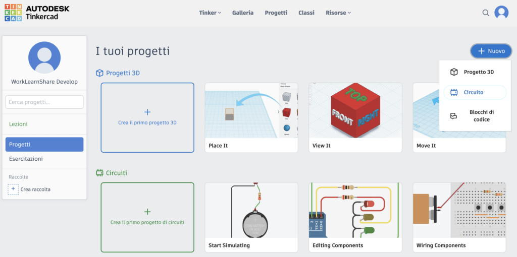
Here you will find a list of all your projects. To create a new one, click the “+ New” button and select the “Circuit” option. At this point, the work area will open, where you can start creating your project by adding components, connecting them, and programming.
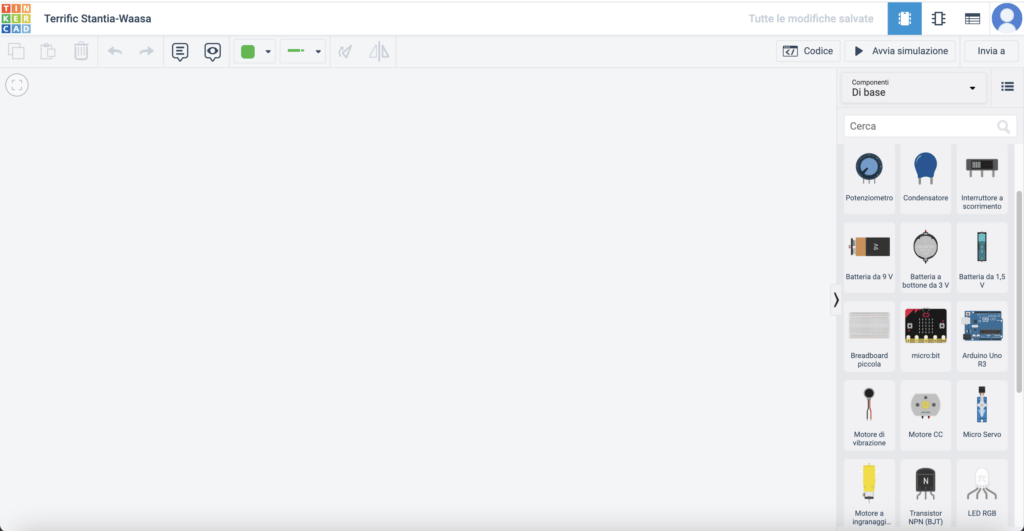
On the left, you can place the electronic components to be tested, which you search for and select from the right column.
To test a circuit with Arduino, in the search bar in the right column, you must type “Arduino”, select the Arduino already connected to the breadboard, and place it in the empty space on the left:
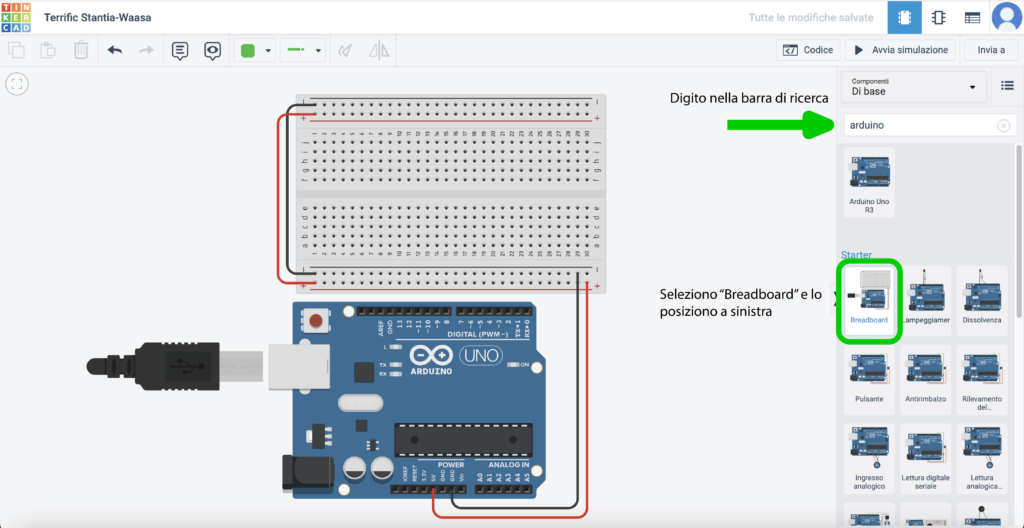
At this point, you will be able to select other electronic components, place them on the breadboard, and connect them through cables that you can draw by clicking on the breadboard holes.
My first project with Arduino: a blinking LED
The first project to get familiar with Arduino is a blinking LED.
Phase 1: Creating the electronic circuit
Shopping bag:
- Arduino Uno board
- USB cable
- Breadboard
- A resistor with a value between 220 Ω and 1 kΩ
- An LED of your choice (red, green, yellow, or blue)
- Jumper cables to make connections
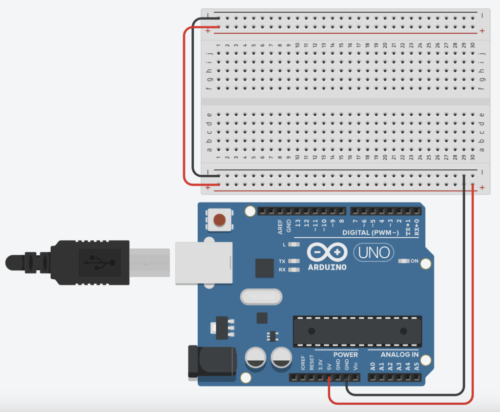
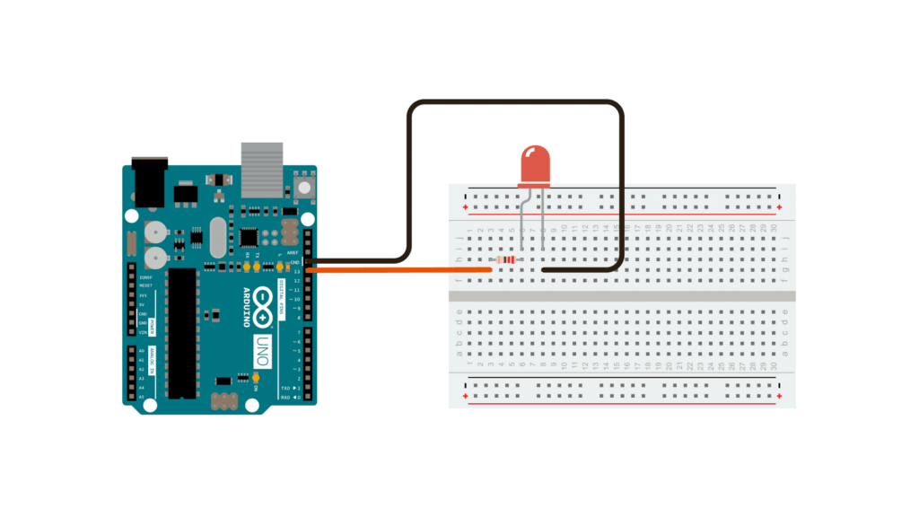
The electrical scheme to be realized is the following:
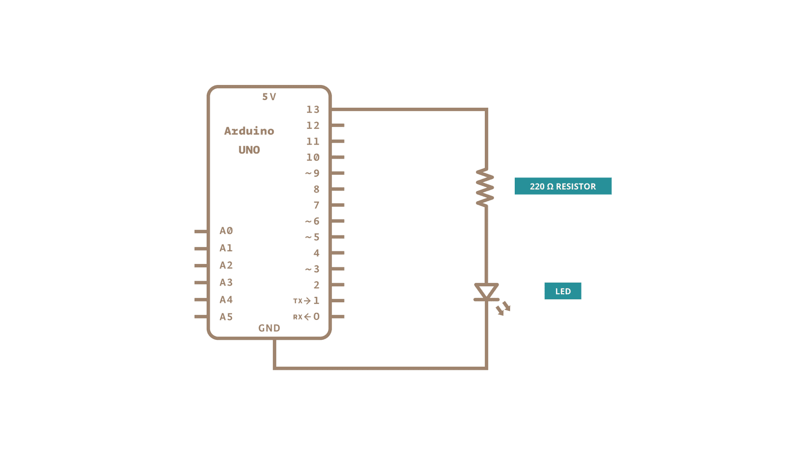
As seen from the functional diagram, the resistor must be connected to Arduino pin 13, after the resistor, the anode of our LED (the + part, the longest LED leg) is connected, and finally, the cathode of the LED (the – part, the shortest LED leg) is connected to ground at the GND pin of the Arduino.
Phase 2: Writing and uploading the program
Before getting into the details of the project, let’s see how an Arduino program is structured.
Structure of an Arduino program
An Arduino program (called a sketch) consists of 3 main parts:
#include "nameOfTheLibrary.h"

void setup(){
//initial steps
}

void loop(){
//part of the program that will be repeated endlessly
}
Just like in the C language, I can call external libraries and define variables that I will use in the program.
The setup() function is the part of the program that is executed ONLY once at startup and serves to define the initial operations that the program must perform (initialization) and to define the purpose of the Arduino pins that I will use (if in read or write mode).
The loop() function is the hot part of the program that will be repeated endlessly (from when I turn on the board until I turn it off).
Fundamental functions to use in an Arduino sketch
Before getting into the code, you always need to identify the Arduino pins you will use and define their mode. In the case of the blinking LED, we will use the digital pin 13 of Arduino in write mode (OUTPUT), as we will turn on (high signal, HIGH) and turn off (low signal, LOW) the LED.
To define the mode of a pin we use the pinMode() function:
pinMode(pinNumber,mode);

//Example:if I use pin 13 for reading (INPUT)
pinMode(13,INPUT);

//Example: if I use pin 13 for writing (OUTPUT)
pinMode(13,OUTPUT);
To write a digital value (HIGH or LOW) on a pin, the digitalWrite() function is used:
digitalWrite(pinNumber,value);

//Example: if I want to write an HIGH value on pin 13
digitalWrite(13,HIGH);

//Example: if I want to write a LOW value on pin 13
digitalWrite(13,LOW);
To make our LED blink, we use a delay function called delay():
delay(valueInMilliseconds);

//Example: if I want to wait 1s
delay(1000);
Full code of our first program
After all these examples, here is the complete code of our first project to make the LED blink every second:
void setup(){
  pinMode(13,OUTPUT);
}

void loop(){
  digitalWrite(13,HIGH);
  delay(1000);
  digitalWrite(13,LOW);
  delay(1000);
}
Test on Tinkercad
To test the program on Tinkercad, proceed as follows:
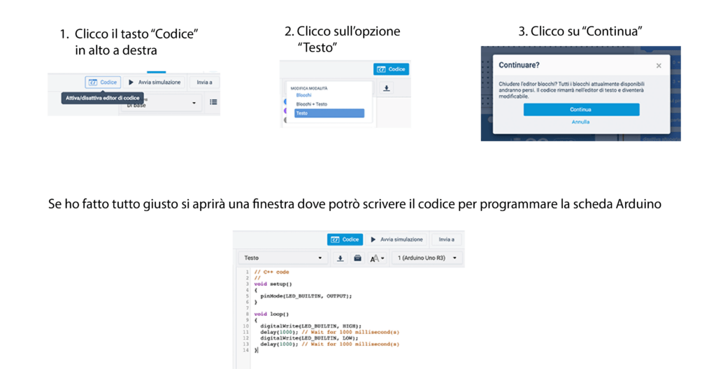
1) Click on the “Code” button on the top right and click on the “text” option. In the message that appears, click on “Continue”. If you did everything right, a window will open where you can enter the code to program the Arduino board.
2) Once you have copied the code, you can test my project by pressing the “Start simulation” button (next to “Code”).
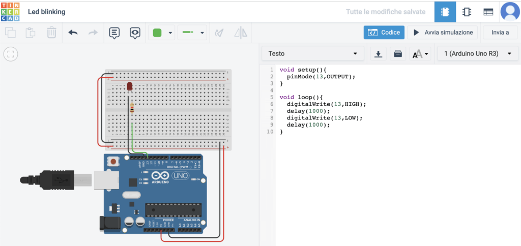
Here is the final project created on Tinkercad:
Test with Arduino kit
To test it using the kit, proceed as follows:
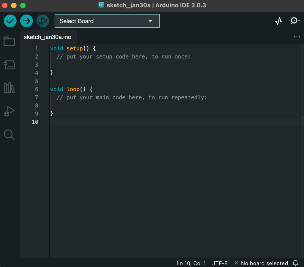
1) Download, install and launch the Arduino IDE program (download link: https://www.arduino.cc/en/software):
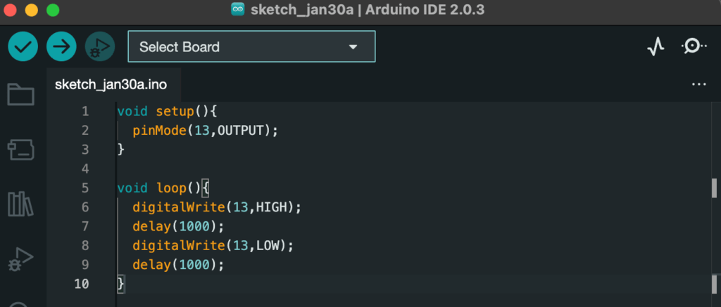
2) Copy the code to the Arduino IDE program:
3) Connect the Arduino board to the PC via the USB cable.
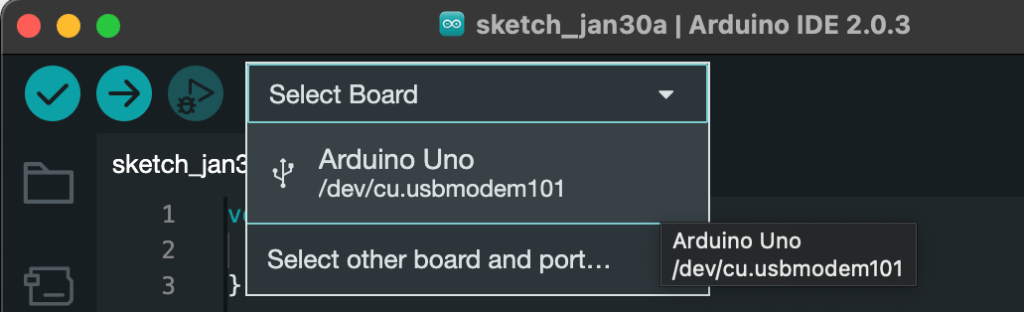
4) Click on “Select Board” and select the USB port to which the Arduino board is connected:
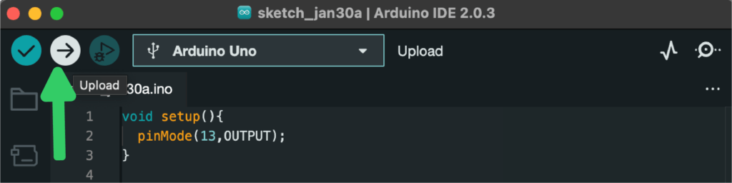
5) Press “Upload” to upload the program to the board:
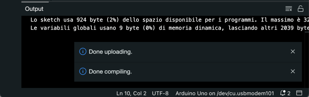
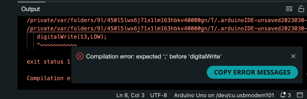
6) If the upload is successful, no message will appear in the terminal. If not, the errors to be corrected in the code will appear in red:
Congratulations! You have created your first Arduino project from scratch 🎉🎉🎉